No. 12of 22StationHardware
Quadruped robot and a custom four-layer controller board
CreeperX robot and mainboard
A 12-servo quadruped robot from a university course, and the controller board I designed afterwards to replace its tangle of breakout modules: four layers, 142 components and three independent 5 A power rails. The board design is complete and checked; it has not been fabricated yet.
- When
- Robot Oct – Nov 2025 · board Sep 2026
- Status
- Built
- Team
- The robot was a three-person RV University course project with a faculty guide. The mainboard is a personal follow-up project.
- Role
- Mainboard: sole designer. Robot: one of three; the Raspberry Pi bring-up logs come from my machine.
Progress
Progress55%
The board design is complete and checked, with 7 short power connections still to route. It is not yet fabricated, and its firmware is compiled but not run on hardware. The robot has camera and servo bring-up only.
What comes next
- Close the 7 open power connections and fix the overlapping silkscreen labels.
- Order five boards and film the first power-up.
- Publish the KiCad project and renders.
142
components on 89 nets, on a four-layer 100 × 100 mm board
A design, not hardware: no board has been built yet.
Netlist and connection list (hardware/creeperx.net, docs/CONNECTIONS.md)Verified. Backed by a file or public page that has been checked.Netlist and connection list (hardware/creeperx.net, docs/CONNECTIONS.md) — Read in the project audit of 13 November 2026. A design-analysis result, not a hardware measurement.7
short power connections still to route
The rest is routed, with no clearance, short or keep-out violations. Overlapping silkscreen labels also need fixing before an order.
Verification notes and design-rule report (docs/VERIFICATION.md, hardware/drc.json)Verified. Backed by a file or public page that has been checked.Verification notes and design-rule report (docs/VERIFICATION.md, hardware/drc.json) — Read in the project audit of 13 November 2026. A design-analysis result, not a hardware measurement.≈ $14.19
parts cost per board at a quantity of five
Parts only, from a check of all 34 part numbers against the assembler’s library. Nothing has been ordered.
Verification notes and BOM check (docs/VERIFICATION.md, hardware/check_bom.py)Verified. Backed by a file or public page that has been checked.Verification notes and BOM check (docs/VERIFICATION.md, hardware/check_bom.py) — Read in the project audit of 13 November 2026. A design-analysis result, not a hardware measurement.96%
of the servo rails' rating in the worst case modeled: standing up from a crouch
A calculated power budget with 6.6 A drawn from the pack, not a measurement.
Power budget script (hardware/power_budget.py)Verified. Backed by a file or public page that has been checked.Power budget script (hardware/power_budget.py) — Read in the project audit of 13 November 2026. A design-analysis result, not a hardware measurement.Exhibit 01 · Layers
The board, layer by layer
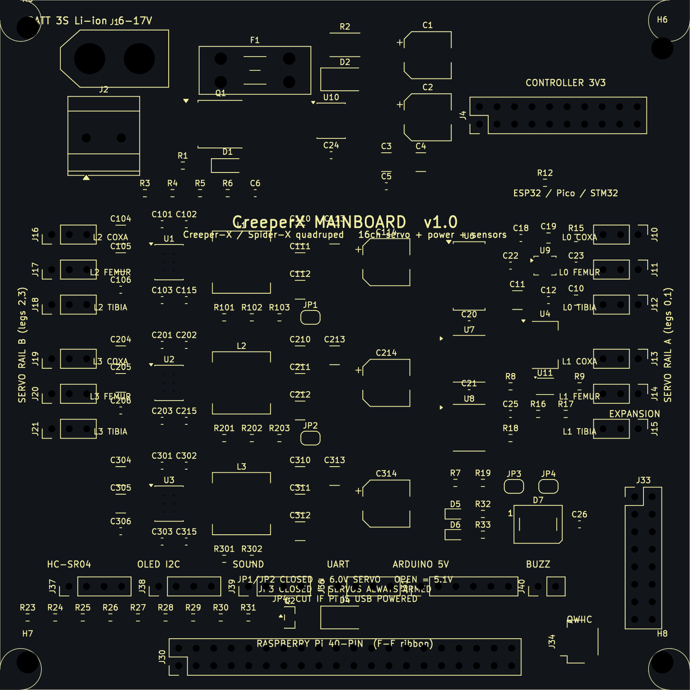
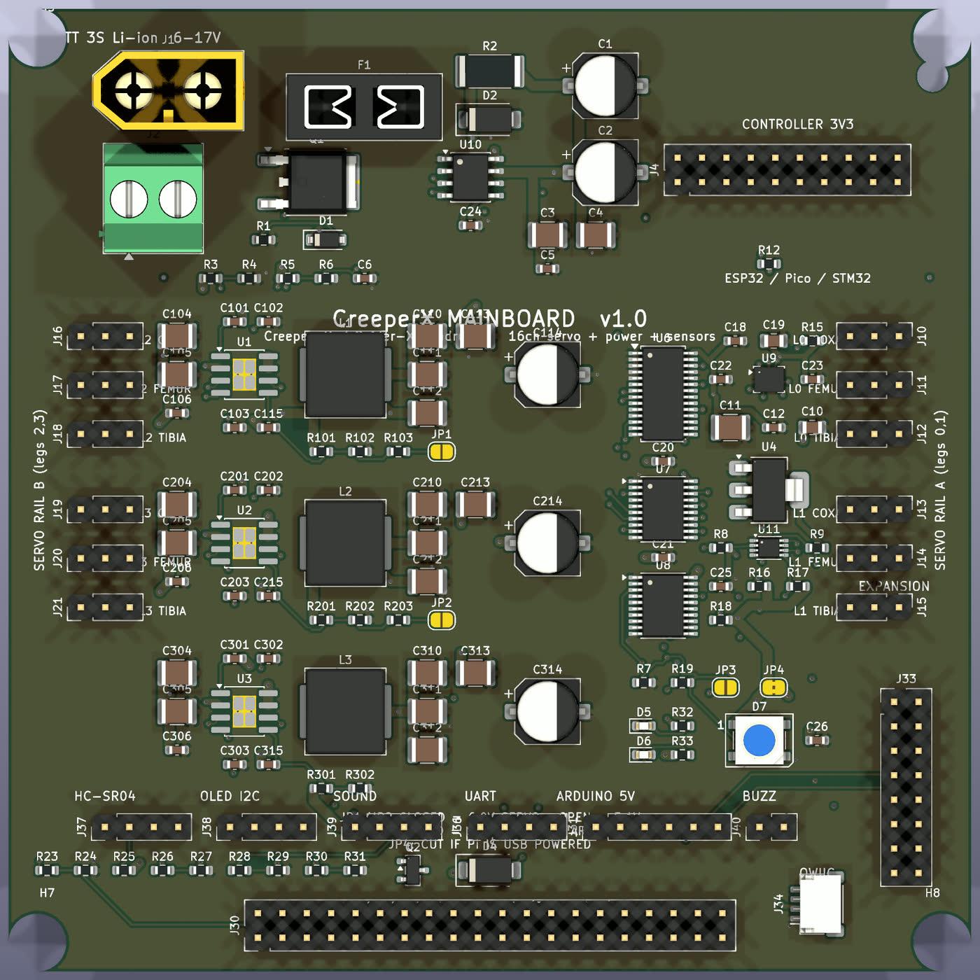
Top silkscreenThe printed labels. A few still overlap, the board title among them; fixing that is on the list before any order. 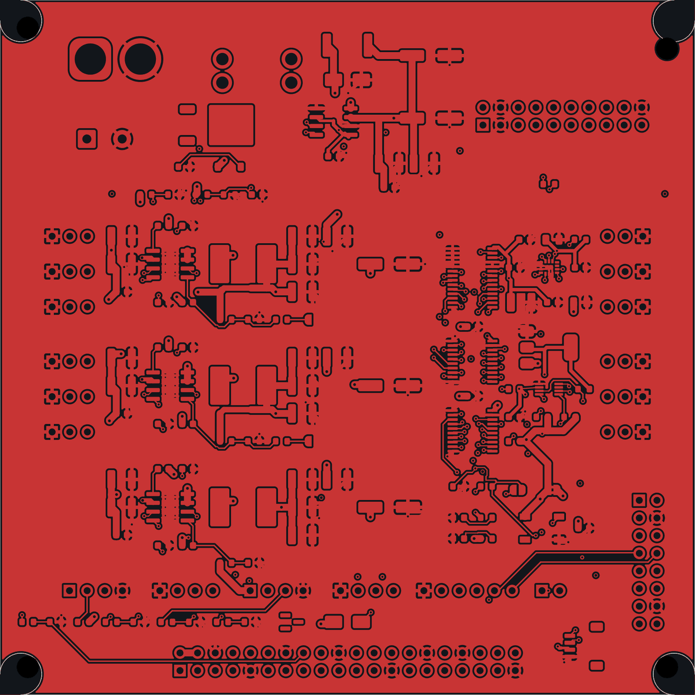
Top copperComponent pads and most of the routing. The three converter stages repeat down the board. 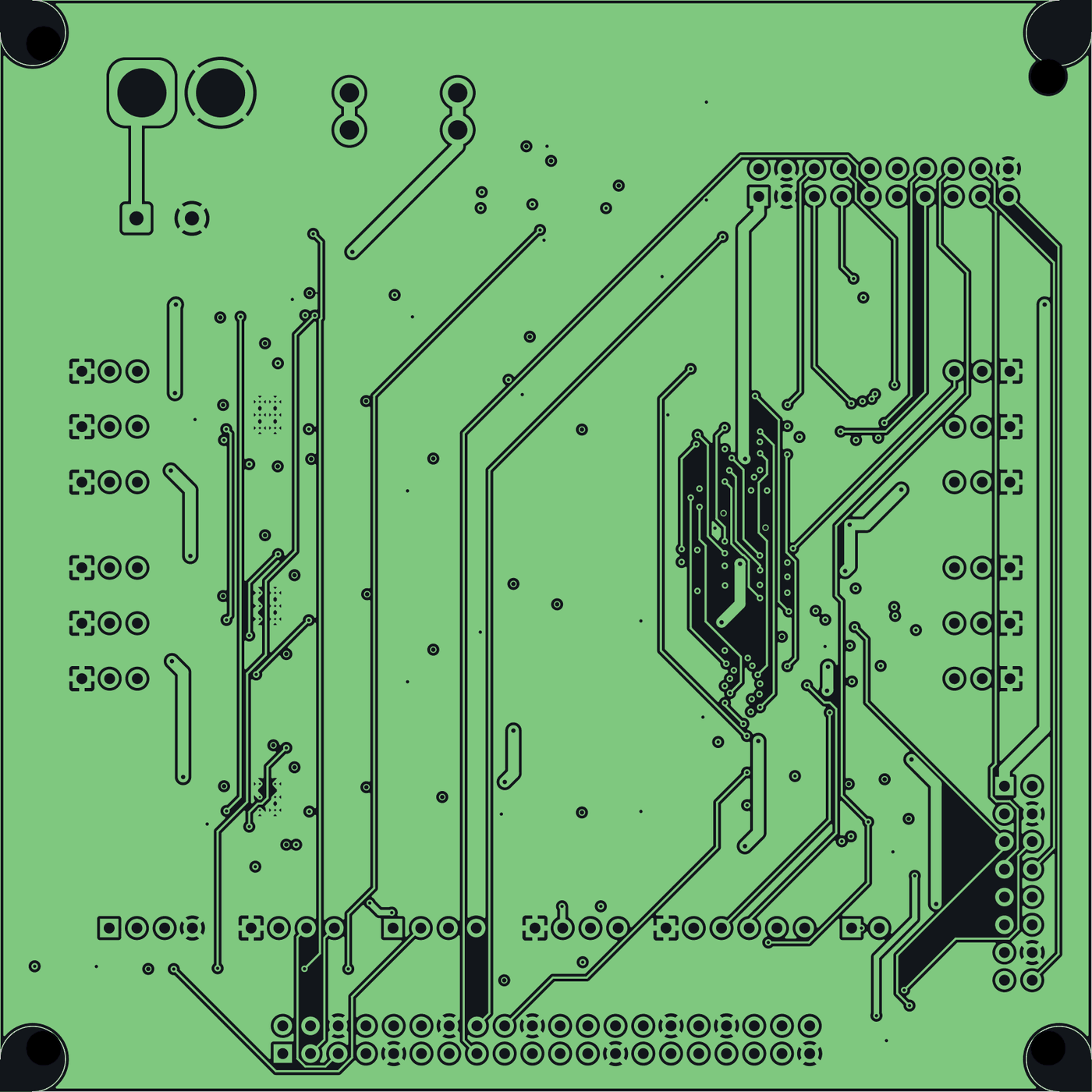
Inner layer 1: groundThe ground plane. 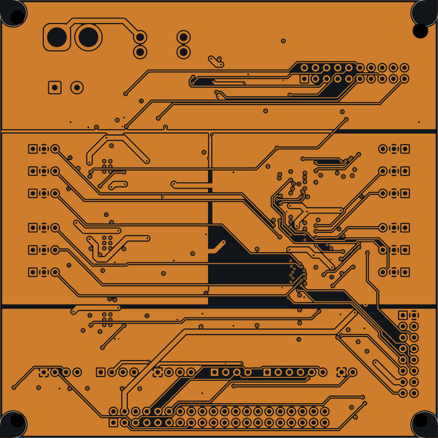
Inner layer 2: powerThe power layer, divided into regions. 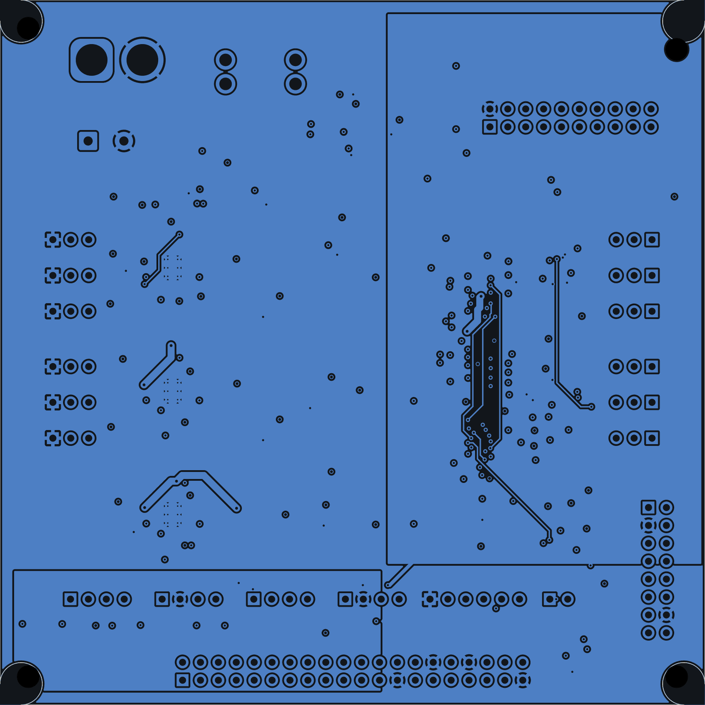
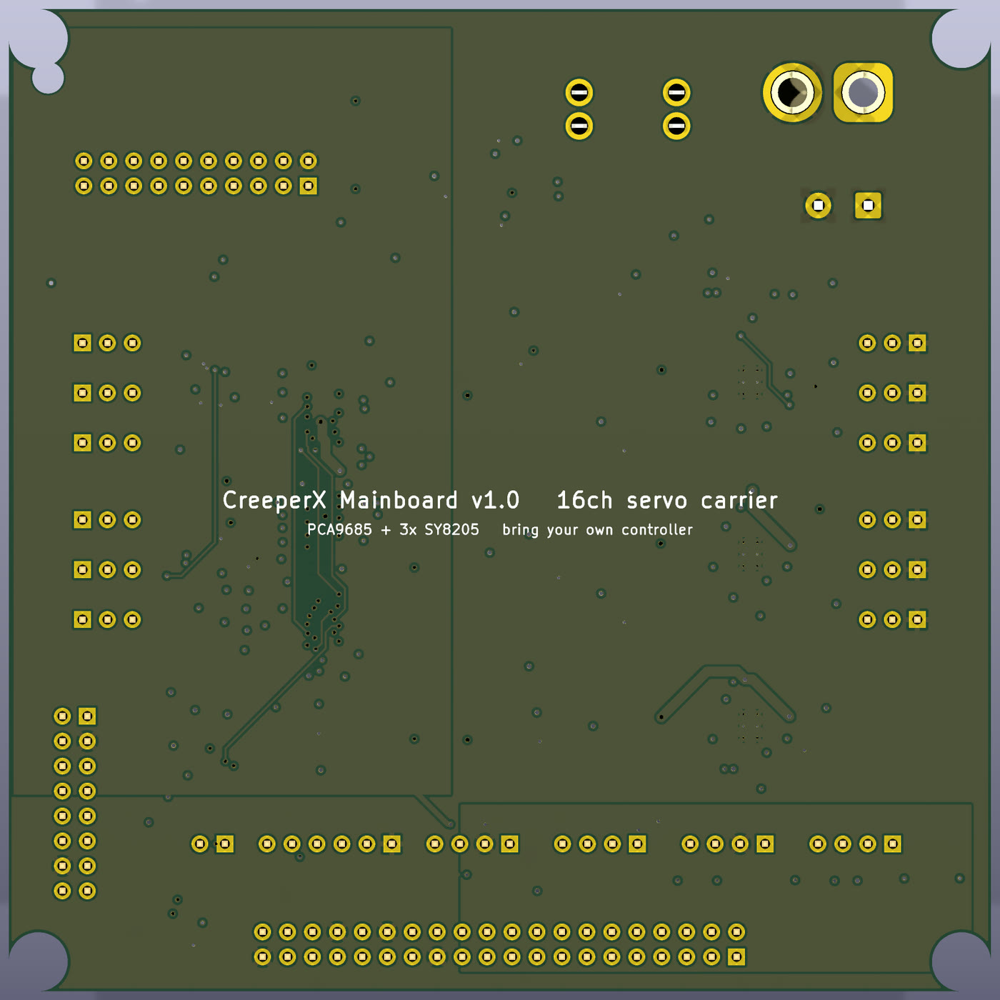
Bottom copperThe rest of the routing.
01 / 05
Top silkscreen
The printed labels. A few still overlap, the board title among them; fixing that is on the list before any order.
Plots from the KiCad design, exported on 13 September 2026 and drawn here on a dark ground. A design: no board has been fabricated.
Exhibit 02 · Scorecard
Design checks, before any board exists
Results from the project's own scripts and verification notes. No board has been built, so none of these is a measurement on hardware.
| Measure | Result | Note | Source |
|---|---|---|---|
| Netlist | 142 components, 89 nets | Connection list and netlist | |
| Electrical rules check | Clean | Apart from deliberate warnings: an LED chain output left open and unused Raspberry Pi header pins. | Rules check report |
| Routing | About 1,430 track and via segments; 7 power connections open | No clearance, short or keep-out violations. | Verification notes, design-rule report |
| Parts cost | ≈ $14.19 per board at five boards | Parts only. 34 part numbers, all in stock when checked. | Verification notes, BOM check |
| Power budget, worst case | Servo rails 96%, 5 V rail 70% of rating | Standing up from a crouch, 6.6 A from the pack. Calculated. | Power budget script |
| Thermal, 25 °C ambient | Servo converters 61 °C continuous, 91 °C peak | Calculated. All parts within their rating. | Verification notes |
| Faults caught before fabrication | 6 silently split nets, 9 colliding reference designators | Found and fixed. | Verification notes |
| Boards fabricated | None | Firmware compiles for the ESP32 and has not run on hardware. | Project audit |
01
What it is
CreeperX is two things of very different strength. The first is a 12-servo quadruped robot, built as a three-person course project in late 2025. The second is the mainboard I designed for it a year later, on my own: one 100 by 100 mm, four-layer board that replaces the robot's pile of breakout modules. The board is a finished, checked design. It has not been manufactured, so nothing on this page is a measurement on hardware.
02
The hard part
The original robot was breakout modules wired to an Arduino Nano or a Raspberry Pi, and its faults were power faults. One small regulator module fed all 12 servos and the controller, with no bulk capacitance. The servo rail was over-volted. The Nano drove 12 servos at the limit of its servo library. There was no battery monitoring, and the servos went live the instant power was applied. The board had to fix each of these without tying the robot to one controller.
03
What was built
Power comes in through an XT60 connector or a screw terminal, then a 15 A fuse, a reverse-polarity transistor, a transient suppressor, and a 5 milliohm shunt that reports pack voltage and current. Three separate 5 A buck converters follow: one for the servos of legs 0 and 1, one for legs 2 and 3, and one for 5 V logic, so a servo brownout cannot reach the controller. The servo rails come up disarmed, behind two independent interlocks. A 16-channel PWM driver runs the servos, and an IMU with hardware free-fall and tilt detection sits on board. Any 3.3 V controller plugs in: an ESP32, a Pico, an STM32, or a Raspberry Pi on its 40-pin header.
The schematic is code. The netlist is written in Python with SKiDL, and placement, the board build, a collision check, the power budget, the design-rule report and the fabrication package are all scripts. Routing was done by an autorouter, Freerouting, plus a repair script of mine. Firmware exists for the ESP32 (a bring-up self-test and a Wi-Fi page to nudge single servos) and as a Raspberry Pi driver. It compiles. It has not run on hardware.
04
What the checks show
These are design-analysis results, not measurements: no board exists yet. The netlist has 142 components on 89 nets. The electrical rules check is clean apart from deliberate warnings. Routing is about 99% done: 7 short power connections are still open, with no clearance, short or keep-out violations. Parts come to about $14.19 a board at a quantity of five. In the worst case modeled, standing up from a crouch, the servo rails sit at 96% of their rating. The same checks caught 6 silently split nets and 9 colliding reference designators before any order was placed.
The robot itself has no results to report. It has a detection script for the Pi camera that uses a pretrained model, and a bring-up sketch for the servos and sensors. No successful detection run is logged, and there is no walking code. The course reports quote accuracy figures that no code, data or model backs, so none of them appear here.
05
What's next
Close the 7 open connections, fix the silkscreen labels that still overlap, order five boards, and film the first power-up. Until then this is a design, and the page says so.
Figures
One question
The answer is on this page. Get it right and it goes in your passport on the map.
Challenge· stamped
The CreeperX mainboard has 142 components on four layers. How many of these boards have been manufactured so far?
None. The design is complete and checked, with 7 short power connections still to route, but it has not been fabricated. Source: the project's verification notes.
Show the answer
None. None. The design is complete and checked, with 7 short power connections still to route, but it has not been fabricated. Source: the project's verification notes.
- Stack
- KiCad
- SKiDL (Python)
- Freerouting
- KiKit
- JLCPCB assembly
- ESP32 (PlatformIO)
- Raspberry Pi 4
- Python
- TensorFlow Lite
- OpenCV
- PCA9685 servo driver
- INA219 power monitor
- LSM6DS3TR-C IMU
- SY8205 buck converters